![]()
![]()
![]()
![]()
![]()
![]()
![]()
![]()
![]()
![]()
![]()
![]()
![]()
![]()
Track Accessories (2 of 3)
Classification of the various kinds of accessories
isn't always clear. For example, the TM Guide calls the #26810
Pow-R-Clips an Electrical Accessory, but the various Track
Terminals that serve the identical function are called Track
Accessories. I deviate from TM by listing the Pow-R-Clips as a
Track Accessory.
In The Gilbert Gallery, Track Accessories
either are mounted on the track or connect track (i.e., track
locks). Electrical Accessories are whistle and horn controllers,
the Lockout Eliminator, wire, rectifiers, circuit breakers, and
the like. The Reverse Loop Relay and Kit defy definition and are
listed both places. Accessories that are integral with track
(e.g., track pins and rerailers) are listed with Track
& Switches. Track Ballast is
another anomaly, listed both here and in Landscape
Accessories. Semaphores, gates, and
crossing signals are Operating
Accessories. Track cleaning fluid is
included among Supplies.
The
Track Accessories are split up over three web
pages:
#27 through #698 are page
1
#704 through #713 are on this page
#728 and above are on page
3
Unless otherwise specified,
the pictures on this page are from the collection of The Upstairs
Train.
If you have a picture that you would like to share
with the world of any of the Track Accessories not shown here (or
a better picture of one that is shown!), email them to me:
theupstairstrain@yahoo.com. Click here
for a list of the pictures I need to complete
the Gallery.
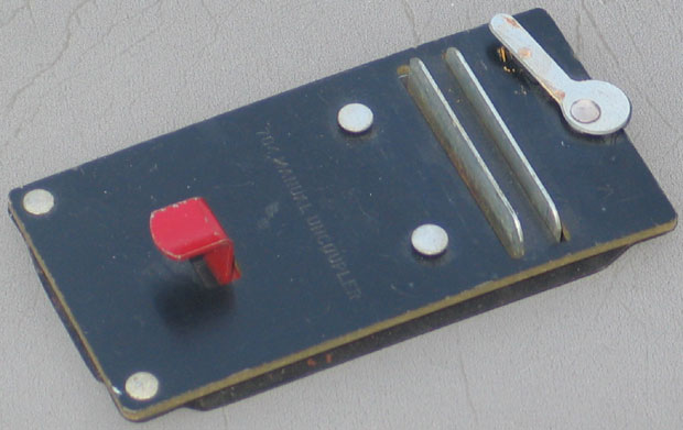
#704 Manual Uncoupler made in 1949 thru 1959.
#705 Remote Control Uncoupler made in
1946 & 1947.
Black housing mounted on a straight track
section with black rails.
(Picture courtesy of Mike
Battaglia.)
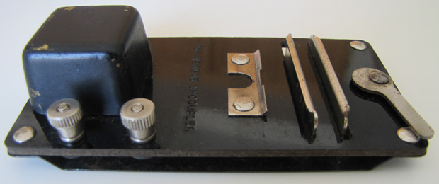
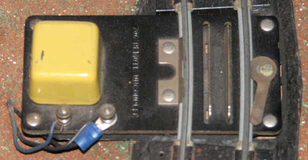
#706
Remote Control Uncoupler made in at least seven variations, of
which Greenberg mentions only five.
The TM
Guide says it was made from 1947 thru 1956; Greenberg and Doyle
say 1948 to 1956.
Above is
the initial, short-lived design. It is not listed by Greenberg.
The solenoid housing was brass painted black; later versions (see
below) were tin painted green or yellow.
Look
closely at the two bars that do the actual uncoupling: their tops
are bent outward;
all the
later versions simply have straight up bars.
David
Dewey offers this commentary: “The housing is brass, painted
black.
The
“flared out” uncoupler bars were soon realized to be unneeded,
and the stamping was more expensive, so the straight bars were introduced.
Tin was
cheaper than brass, and I imagine the green and yellow covers came
about to match other accessories
or to
attract Mom’s eye—Moms made many of the toy train
purchases, and AC recognized that.”
Doug Peck
reports that he has a couple of these with black brass housings
but straight up bars.
Gilbert probably had an inventory of
brass housings to use up when they changed the design.
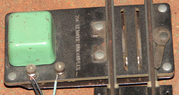
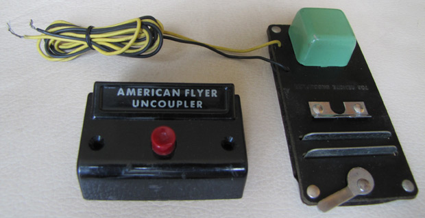
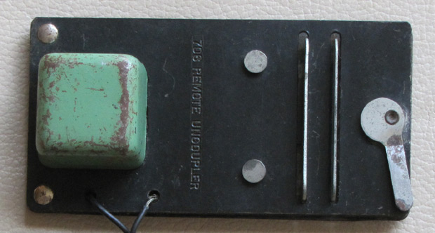
Greenberg
called this “Variation A.” Note the straight up
uncoupling bars.
It has a green tin housing, binding posts for the wires, and a sheet metal strip
securing it to the rail.
Those are the three things that
distinguish the five variations documented by Greenberg.
Variation B is the same except the housing is yellow.
Variation C is the same as Variation
A except it has wires permanently connected instead of binding
posts.
All five variations came with a
black-body control with a red button and white lettering.
Variation D is the same except the housing is yellow.
 Variation
E is the same as Variation C but it is secured to the rail by two
pins rather than a sheet metal strip.
Variation
E is the same as Variation C but it is secured to the rail by two
pins rather than a sheet metal strip.
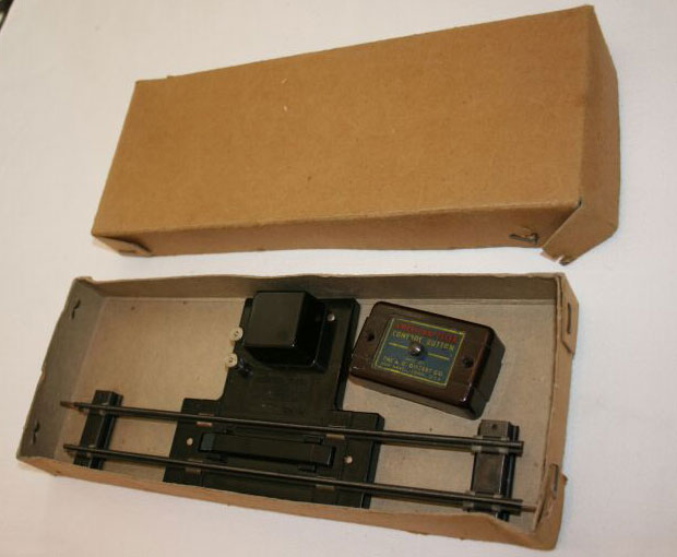
Initially,
Gilbert included a piece of straight track with each uncoupler and
packaged them in a long box.
If anyone has one of those boxes
and can send me a picture, I'd appreciate it.
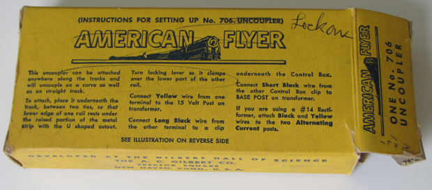
Later,
no track was included and it was packaged in a small box with
instructions printed on the top.
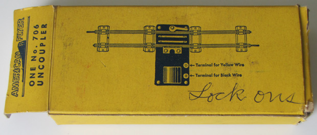
Printed
on the bottom of the box was a drawing of the uncoupler.
This
box was for Variation A or B – note the binding posts.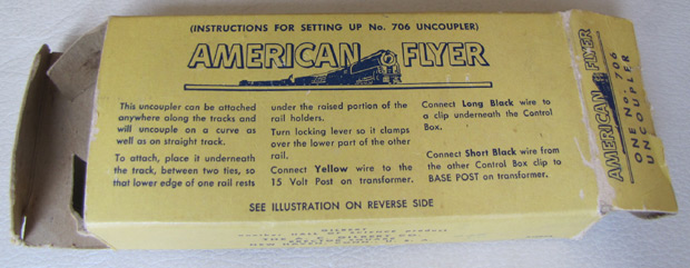 This
is a later box; note that the Rectiformer instructions have been
deleted.
This
is a later box; note that the Rectiformer instructions have been
deleted.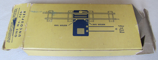 Printed
on the bottom of the box was a drawing of the uncoupler.
Printed
on the bottom of the box was a drawing of the uncoupler.
This
one is for variation E – note the two rail holder pins.
The
drawing appears to have two binding posts, but the
verbiage refers to the connected wires.
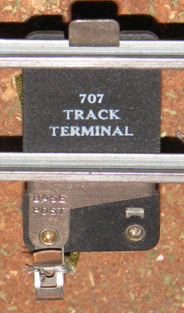
#707 Track Terminal
made in 1946
thru 1959.
It is used with a semaphore,
or in some other
situation that requires connection to only one rail.
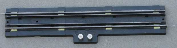
#710 Automatic Track Section with two inside contact rails made in 1946 & 1947.
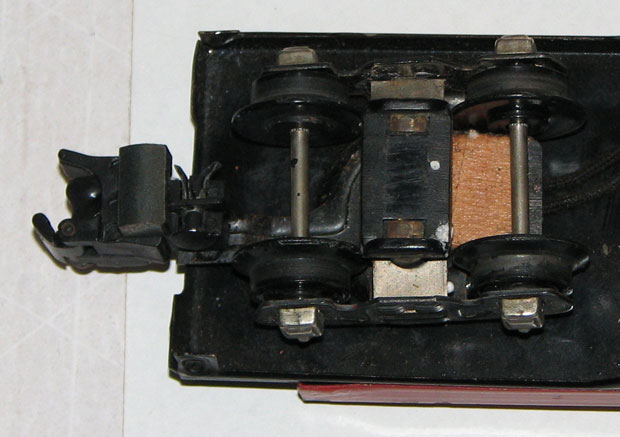
Operating cars made in 1946 had an
inside power pickup like this.
The two inside rails of the #710
Automatic Track Section provided power to these contacts under
car.
#711 Mail Pickup with two inside
rails for contacts made in 1946.
It's similar to the #713
Special Rail Section below,
but has two inside rails like the
#710 Automatic Track Section above rather than the outside rail of
the #713.

#712 Automatic Track Rail made in
1947 thru 1957.
It was sold with a variety of operating
boxcars, flatcars, and hopper cars.
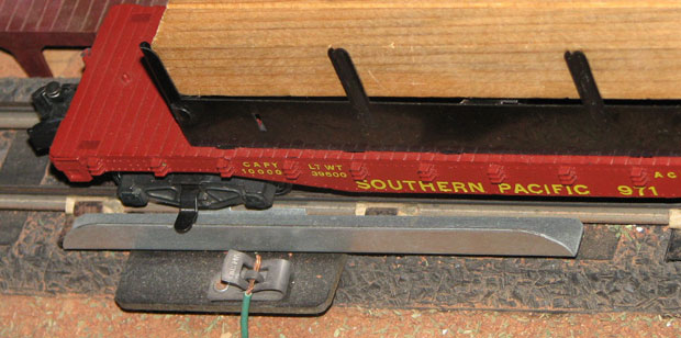
Here it is with the #971 Lumber
Unloading flatcar.
The car gets one side of its power from the
rail connected to the transformer's Base Post.
The other side
comes from the #712 Automatic Track Rail via a finger sticking out
from one truck.
The wire connnects to the operating button that
comes with the car.
To operate one of these cars, stop the
train with the car's finger on the #712 Automatic Track Rail
and
push the button.
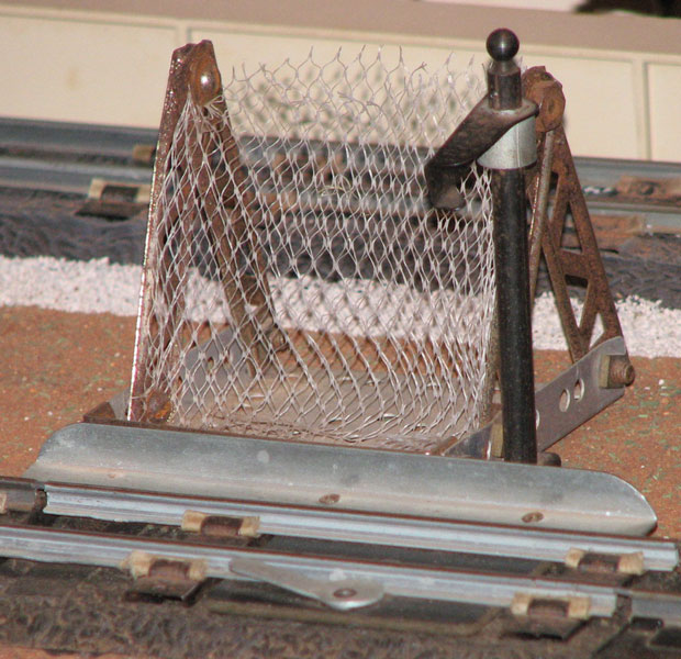
#713 Special Rail Section made in
1947 thru 1958. It was sold with the #718
and #918 Mail Cars.
It's identical
to the #712 Automatic Track Rail except that it has an arm
sticking up
to hold a mail bag for the passing mail car to pick
up.
Behind it is the mail bag catcher my dad and I made from my
Erector Set when I was a kid.
Unlike the other operating cars,
the mail cars operate with the train moving.
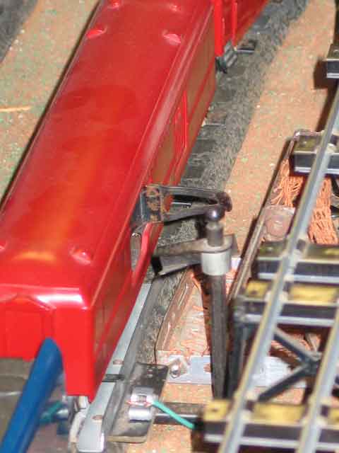
The Mail Car tosses one mail bag out and grabs
another off the #713 pickup arm as it passes by.
It's a
wonderul thing to watch!
Notice the power pick-up finger
extending out from the truck as it does on the flatcar above.
It takes time and money to maintain a website
like this. If this site is interesting and helpful to you,
please contribute financially to its ongoing success. You
may send
a contribution via PayPal using
theupstairstrain@yahoo.com as the payee. Both credit card and
direct transfers would be greatly appreciated. Thank you very
much.
If you or your friends have some American Flyer
trains and would like them to go to a nice home where they'll be
loved and cared for, this is the place! Email me:
theupstairstrain@yahoo.com. See my Wish
List for the items I need most.
Thank you very much.
On the other side of the coin, I post
pictures from time to time on my For
Sale page of surplus items I have for
sale.
This gallery will continue to grow and become more
comprehensive as I collect more equipment, and as visitors send me
pictures of the items I don't yet have. If you have a car,
engine, accessory, or set that you would like to share with the
world, email me a picture:
theupstairstrain@yahoo.com. Click
here for a list of the pictures I need
to complete the Gallery.
The books I am using for reference
are listed in the Bibliography
page. All the writing and all the pictures on
this website are, however, my own, except where cited. No
copyrighted materials have been included and all pictures provided
by others are used by permission.
Now show me:
The
Gilbert Gallery Home Page
Engines
Passenger
Cars Freight
Cars Accessories
Infrastructure
Track
& Switches Track
Accessories Transformers
Electrical
Accessories
Bulbs
Couplers
& Trucks Supplies
Pictures
Needed Useful
Links For
Sale Wish
List Bibliography
The
Upstairs Train
![]()